System Architecture
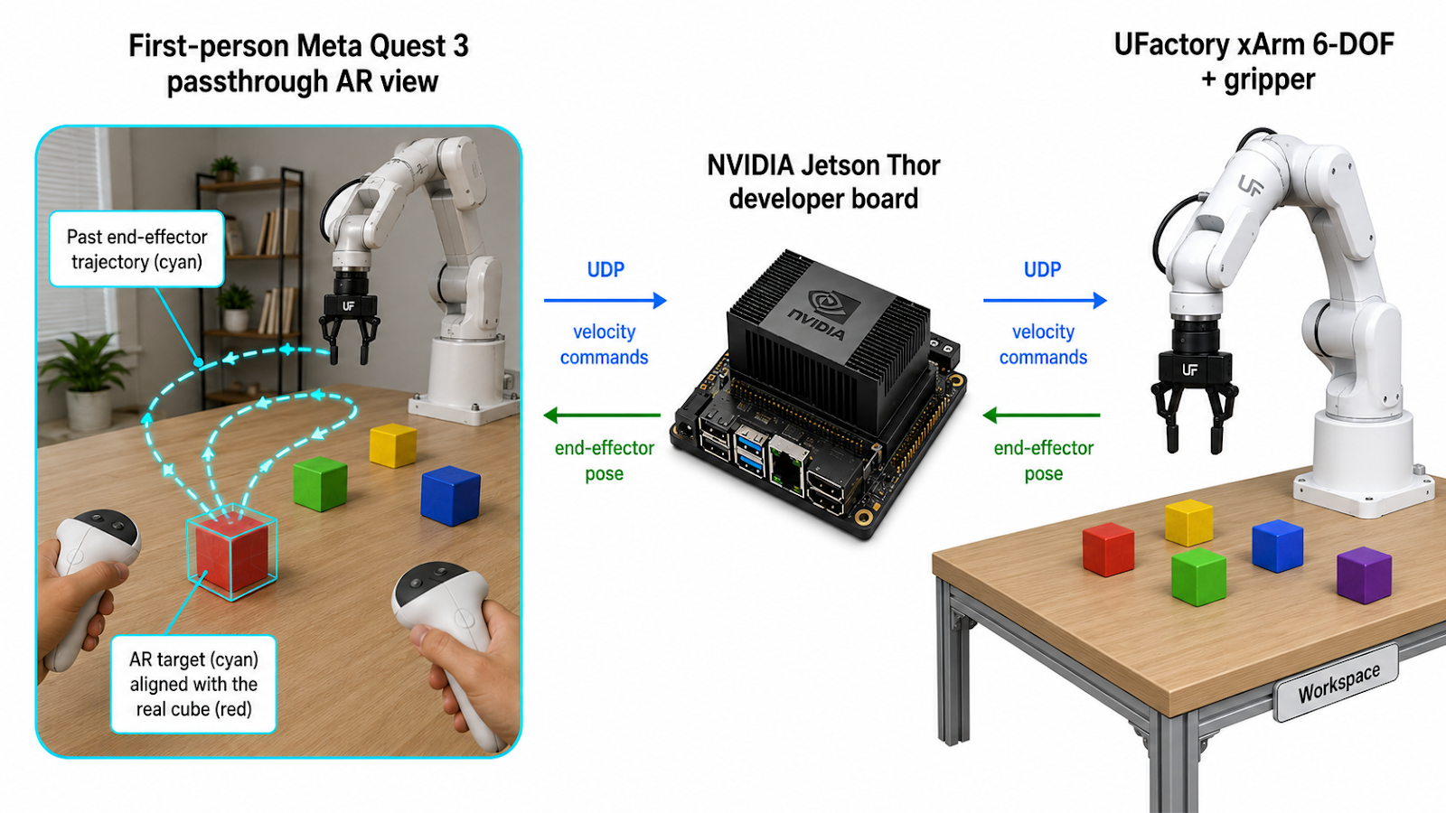
Image generated by OpenAI Image2
Quest 3
AR + Control
AR + Control
UDP
↔
↔
Jetson Thor
Bridge
Bridge
ROS2
↔
↔
xArm 6-DOF
Executes
Executes
Power on xArm, connect Jetson via Ethernet. Connect Quest 3 to Jetson via WiFi Direct. Launch xArm ROS2 driver and bridge on Jetson. Deploy the Unity app to Quest 3.
Put on the headset — the real world is visible through passthrough. Place the left controller at the robot arm's base, pointing forward. Press X to calibrate. RGB axes appear at the origin, and the first target cube is generated at a random reachable position.
A small semi-transparent colored cube with a numbered label and black wireframe edges appears in AR. The operator places a real physical cube at that position, aligning it with the AR overlay.
Hold right trigger to teleoperate — hand motion maps to robot velocity. Press grip to close/open the gripper. The trajectory draws in real time (cyan line). Blue/yellow markers appear at grasp/release points.
Press A to stop recording. The trajectory is frozen. Reposition the arm to a new starting pose. Press A again — the old target fades, a new target appears at a different random location, and recording resumes. All historical trajectories stay visible. Press Y to clear everything and start fresh.
| Visual | Meaning |
|---|---|
| ● Red sphere | Live end-effector position |
| ━ Cyan line | Trajectory during current trial |
| ■ Blue cube | Where the gripper closed (grasp point) |
| ■ Yellow cube | Where the gripper opened (release point) |
| ■ Colored target | Randomized grasp target with number label |
| ■ Faded targets | Completed trials (history stays visible) |